Update: March 9th-23rd and Next Steps
- Mar 23, 2024
- 8 min read
On March 8th, the team received the final machined parts for the vent displayed in Figure 1. Mostly everything in the machining went according to plan and the parts came out as the team expected. The only two things that the team needed to address were the set screws used to assemble the vent lid and the vent case, and the pins on the pulley system. The set screws are a bit too long so they don’t flush with the vent lid. The team has found alternative screws that will be purchased and used for the final assembly of the vent. However, the set screws from the machinist can still be used during the first assembly and testing, and for the project demo. The issue with the pins on the pulley system is that they don’t have a groove, making it hard for the wire to stay on once it is installed. The team is planning on solving this by using a knife and scissors to create small groves for the wire to sit on. The pulley system is one of the trickiest parts of the vent assembly. The team therefore decided to test all other functionalities of the vent first before trying to implement the pulleys. For the first rounds of prototype testing, the team attached the SMA wire to the vent and let the wire run through the gap where the pulley system will be placed, and then attached the wire to a testing stand. More about this setup will be explained later.

Figure 1: Machined vent components for the final prototype
The team has also finalized and tested the code and components for the control system. In the previous work period, the team completed PWM parameter testing and made the selection for the final values to be used in the project. The final selection is 5 [V], 1 [A], 10 [Hz], 1.1 [s] heating time at 30% duty cycle for opening, and 10% duty cycle to hold the vent open. This selection gave a maximum contraction of 3.4 [mm] in 1.1 [s] which indicates that the vent will achieve the maximum vent opening goal (3-5 [mm]) and the actuation time goal (less than 10 [s]). The duty cycle for holding the vent open was first selected to be 1%. However, this proved to be too low to power the SSR input when the connections were corrected. It was adjusted to 10% and everything worked as planned. The code and wiring to implement a temperature sensor to trigger the control system were also implemented. The final setup for the control system is provided in Figure 2. This also includes a testing setup for the vent. The selected components that will be used are an Arduino Uno microcontroller, a DC/DC solid-state relay, a power supply, a DS18B20 temperature sensor, an LCD display, alligator clips, and cables/wires.

Figure 2: Control system setup connected to the vent testing setup
The team is also close to finishing the fabrication of the battery testing case. The progress of the case is displayed in Figure 3. The enclosure is crafted from UHMW Polyethylene held together by rivets and aluminum angles. In order to keep the system closed the outside edges were covered with aluminum tape and the inside edges were covered with silicone in order to prevent thermal leaks from inside the chamber. The lid will be implemented using hinges and sealing putty, the hinges will allow for easier access when installing the vent and the putty will ensure there is a proper seal when closed. In order to maintain the lid closed, the remaining three sides of the lid will be held down with latch-like mechanisms. The use of the battery chamber is intended for validation testing of the vent system, simulating its use with lithium-ion batteries. This case and a hot air blower will be used to simulate thermal runaway and test the functionality of the vent. Extra holes for the hot air blower and sensors will be added in accordance with the final assembly of the whole project.
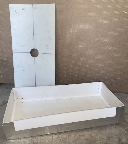
Figure 3: Current state of the battery pack chamber for testing.
The team has also worked on implementing the SMA wire in the final vent prototype and integrating the control system. A testing set-up was created to test the functionality of the passive and active opening of the vent using the SMA wire without implementing the pulley system. The team was successful in these tests. The vent can open both actively and passively, and the springs that are integrated into the vent proved to be strong enough to close the vent upon activation. The control system works great and is only triggered when the temperature rate of change exceeds 25 C/min as planned. Figure 4 shows the open and closed state of the vent in the testing setup using both passive and active openings. The passive opening was tested with a heat gun directly heating the wire. The active opening was tested by triggering the code using the heat gun on the temperature sensor. Everything worked as planned. The only issue is that the vent is occasionally unable to fully reseal after activation. This could be due to a slight machining error as the vent case and vent lid do not match together completely when assembled which interferes with the vent closing.

Figure 4: Testing for passive and active opening
For the work period of March 24th to April 6th, the team’s priority is to finalize the integration of the wire in the vent, finalize the prototype, install it in the vent case, and start the validation testing. The only thing that is left for the integration is to make the pulley system work. This has proven to be a very tricky task because of the small scale of the vent. The team will do their very best to solve this integration problem and make the pulley system work. If this is not possible, validation testing on the project can still be completed, but the vent would not be fully functional for integration in a real lithium-ion battery. Once the integration is completed, or if the team deems that they will not be able to integrate the wire in the pulley system, the validation testing will begin.
The design’s success will be evaluated through a series of tests quantifying the performance of the SMA Actuated Safety Vent. The vent will be installed in the testing case with a hot air blower inside that will be used to simulate thermal runaway since testing with real LIBs is both dangerous and expensive. The SMA’s minimum recoverable strain, which is the ability of the SMA wire to deform and return to its original shape upon phase transformation, will be measured separately before implementing the wire in the vent. This will be tested by measuring the SMA wire in its fabrication shape, then deforming it at room temperature (martensite phase) at strains from 3% up to 6%. Next, the SMA wire will be heated past its transition temperature to activate the shape memory effect returning the wire to the austenite phase and opening the vent. The team will then measure the wire again and compare the recovered length with the original length before initial deformation. The wire should be able to recover the shape fully on strains up to 5%. The first constraints/goals that will be measured when the vent is implemented in the testing setup are the SMA transition temperature and active opening activation point. The transition temperature (passive opening) should be 70 [°C] ± 5 [°C], and the active opening should be triggered when the temperature sensor senses a change equal to or greater than 25 [°C /min] which corresponds to an increase from 35[°C] to 60[°C] in less than 1 [min]. To verify the passive opening, thermal runaway will be simulated using a hot air blower inside the battery chamber to increase internal temperature. A DS18B20 temperature sensor connected to the control system and in close proximity to the SMA wire will be used to monitor the temperature and display it on an LCD (display screen). The wire is considered activated when it starts contracting and the vent should open when the sensor reads temperatures at 70°C ± 5 [°C]. For the active opening, the temperature in the battery case will be increased using the hot air blower while the DS18B20 will be placed in a glass of ice water. The sensor will then be reintroduced into the battery case to simulate the extreme conditions of rapid temperature increase found during thermal runaway. The display will be monitored to verify that the active opening activates when the rate of change reaches 25 [°C /min]. SMA will then be heated to 70 [°C] through an electrical current to provide actuation. The SMA transition temperature for closing will also be noted when the temperature starts decreasing and the wire deforms again from springs counteracting it.
The next verification step is the vent’s actuation time, maximum vent opening for both passive and active opening, and the SMA plastic deformation. Passive opening time will be validated through a stopwatch from when the internal temperature reaches 70[°C] ± 5 [°C] (see LCD) to when the vent reaches its fully open state of 0.34 [cm] lowering from the initial position. For the active opening time, the validation will consist of timing from when the temperature sensors detect a rapid increase in internal temperature equal to or more than 25 [°C/min] to when the vent reaches its fully open state of 0.34 [cm] lowering from the initial position. Both activation times should be within 10 [s] from the closed to open state. The maximum vent opening will be verified in this experiment using a digital caliper or a proximity probe. Complete closure after activation will be measured using a proximity probe. Starting at the closed position the team will record the value from the vent to the proximity probe. The vent will then complete a full opening cycle and return to the closed state. The value after activation should be the same as the value before activation to reach the 0 [mm] plastic deformation goal. To ensure that the vent mechanism can be used for educational purposes for at least 15-20 years, the fatigue of the SMA wire and the steel springs will be measured. The team has purchased enough SMA wire and springs that there is enough to use for fatigue testing. The vent mechanism will be set up in the 3D printed vent, and the control system code will be set to run 5000 cycles to activate the wire and the springs to the desired fatigue life. The activation time, maximum contraction, and final vent position will be measured to ensure no decline in performance. If the 3D-printed model cannot tolerate 5000 activations, the team plans to build a separate simple setup to activate the wire and the springs together in similar conditions to what is found in the vent. Lastly, the team will verify that the weight of the venting mechanism does not exceed 0.5 [kg] by placing all the components of the vent and control system on a scale.
The team’s main obstacle is the integration of the wire into the pulley system. The team has a plan for device assembly, but the vent’s small scale makes integration more difficult than anticipated. The team plans to get some advice from Dr. Gangbing Song and Dr. Agrawal after the demo, to decide on a solution for successful integration. However, if this does not work, the team can still perform validation testing of all other functionalities of the vent using the testing setup displayed in Figure 2 and Figure 4. Depending on the outcome of future pulley integration attempts, Team Navy may proceed with this setup.


Comments