Semester Recap
- Nov 25, 2023
- 6 min read
Updated: Nov 25, 2023
State of the project and future horizons
November 25, 2023 - By Hedda Grelz, Andres Calderon, Oselumenosen Ekhuemelo, and Adolfo Diaz
Work Period Nov. 11 - Nov. 25:
During this work period, the team focused on updating the design based on recommendations from the machinist to ensure that the fabrication of the design is feasible and does not require the team to go to an outside machine shop as this would not fit in the team’s budget. In addition to this, the team has worked on finalizing analysis to support the design and perform SMA testing on the selected wire for load analysis completion. The SMA testing was meant to verify some specifications requirement and measure the force needed to strain the wire and the maximum generated actuation force. The set up for this experiment was explained in the team’s previous blog. The test data was crucial to complete the spring analysis and FEA. It also allowed the team to come close to finalizing the budget with exact spring selection. The FEA and heat transfer analysis were also done, and the results are explained below. Some minor adjustments will be made for the final design review, but the main results are not expected to change drastically.
The focus moving forward towards the end of the semester is to finalize the pulse width modulation (PWM) requirements for the control system to enable the team to make final selections of the control system components. The team will focus on determining the pulse-width and duty cycle required to actuate the wire, and then to hold the vent in its open position.
Key design features:
Shown in Figure 1 is the team’s progress on the design since the last update. The old design (a) had to be modified due to flaws pointed out by the machinist, these suggestions led to the most current (b) and hopefully final design. The most noticeable change is the vent, since the holes were too small to machine, along with the thickness of the inner cylinder wall being too thin. This led to a complete change in the design of the vent part as shown. A change was also made to the steel spring holders since the wall thickness of the spring housing was too thin.
One of the crucial design aspects of this project is to keep the vent within the required dimensions of 2.5 [cm] in height and 5 [cm] in diameter. This makes the machining difficult and the team therefore spent a lot of time updating the design to stay within these constraints while creating a feasible CAD. The team decided to make the holders go through the inside of the spring rather than holding it through the outside diameter to make machining easier and provide better stabilization for the vent when being pulled down. The stabilization comes from holes on the underside of the vent that align with the guide/spring holders as shown (c). In order to keep the gases from exhausting out too fast from the inside of the battery pack, the vent holes were still implemented but on the vent case rather than on the vent. Finally, the floor of the vent case was expanded to elongate the distance between the pulleys. This allows the team to easily fit the necessary 8.84 cm of SMA wire inside the vent. The new design (b) should be able to be machined without having to use a third-party machinist. The overall vent weight is estimated to 0.157 kg which is less than the teams target of 0.5 kg.
The springs are another key design feature. SMA testing and analysis has been performed to ensure that the springs can be compressed when the wire is heated and actuated but will be strong enough to counteract the wire in its cold phase and reseal the vent. This is crucial for the educational use of the prototype post fabrication.
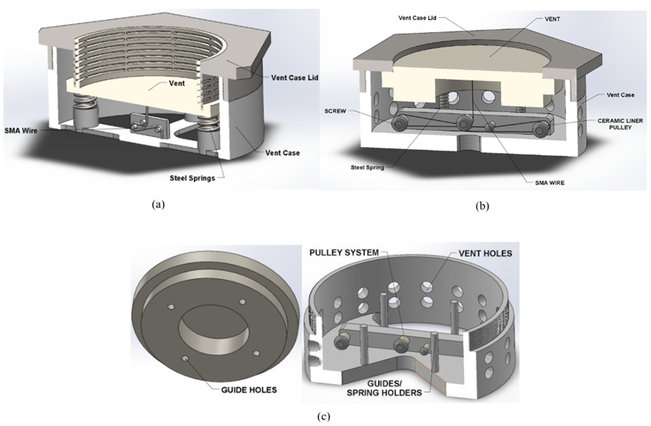
Figure 1: (a) design reviewed by machinist, (b) updated design based on shortcomings, (c) key design features of updated design.
One of the main novelties introduced by team Navy in this project is the active venting. The control system design is crucial to ensure that this function works properly. Below are some highlights from the current control system design and explanations of how it contributes to an effective solution.
Team Navy plans on using Pulse Width Modulation (PWM) to enable active control of their safety vent. PWM typically involves a carrier wave, command signal, a bang-bang trigger, and a saturation block as seen in Figure 2. A carrier wave generator produces a triangular carrier wave which has a significantly higher amplitude than the command signal [1]. These signals meet at the sum block, where a positive difference between the signals corresponds to the d on-state; likewise, negative wave differences result in the d-h off state [1]. Additionally, the team plans to implement a saturation block to prevent overheating during joule heating, due to output overshoots.

Figure 2 - Pulse Width Modulation Diagram
Figure 3 displays the team’s overall envisioned solution to Control System Modeling, which they plan to implement during the next semester. The temperature sensor detects temperature changes corresponding to Thermal Runaway (TR) in the battery case and sends a trigger to initiate active control. Additionally, the team added a displacement sensor to ensure positional stability during device operation. Finally, the low pass filter acts as a means to filter high frequency ‘noise’ that may arise from the displacement sensor.

Figure 3 - Block Diagram Schematic
Key analysis results:
The team has conducted three major analyses: control system modeling, SMA testing, and some smaller volume and weight calculations to ensure that all specifications and project constraints are met.
The team conducted a 2D conduction heat transfer analysis to estimate the volume of the battery that can be covered by a single vent. The industry requirement is that the vent should open before the point of TR ignition which happens around 110 °C. The SMA vent actuates at 70 °C. The heat transfer analysis was therefore used to determine the radii around a battery at ignition which reaches 70 °C. If the battery at ignition is in the center of the battery pack, the radii at 70 °C is 0.6 m. The team will therefore create a testing case that is 0.6 m long. In a full-size car battery, at least 2 vents will have to be used for full coverage.
The team also did SMA testing to determine how much force is needed to stretch the wire 4% of its original length and the maximum amount of actuation force the wire can generate when heated past its transition temperature. The selected wire has 0.25 mm diameter. The team determined that the force needed to stretch the wire was 7.71 N and the maximum actuation force without remaining plastic strain was 12.60 N. The actuation time was less than 1 s which is well under the team’s goal of under 10 s activation. From these results, the team performed a load analysis on the vent to determine the design conditions for the springs which will be used to counter the SMA force and reseal the vent after actuation. From the determined conditions, springs from a stock spring vendor were selected that fulfills all requirements. The team will use four music wire springs in the design with the following specifications:
· k = 683 [N/m] – spring constant
· zi = 7.95 [mm] – free length
· zs = 2.74 [mm] – solid length
· do = 2.24 [mm] – outer diameter
The results from the load calculations were put in to a 2D FEA model of the SMA wire. The results from this are shown in Figure 4. This models the pre-strain, heating the wire to open the vent, cooling, the springs acting to reseal the vent, and then heating it again to open it. The only thing that needs to be adjusted in this model is to add a boundary simulating the vent case such that the strain doesn’t exceed 4% even when additional stress is added.

Figure 4: Results from FEA after spring load analysis
Setting the stage for Spring 2024 (Capstone II)
In preparation for the spring 2024 semester, the team has achieved significant milestones. They have successfully defined the problem at hand and delved into comprehensive research by examining existing literature. Clear project scope and objectives have been established, providing a solid foundation for the upcoming work. To evaluate the feasibility of the project, the team conducted various analyses, including Finite Element Analysis (FEA) on the Shape Memory Alloy (SMA) wire, a heat transfer analysis to determine the vent coverage area, and a spring analysis to identify the necessary characteristics. The design concept has been not only finalized but also refined for the fabrication stage, demonstrated by the completion of a detailed 3D model using Solidworks. The team has taken crucial steps in material selection for the vent components and has identified additional resources required for testing and fabrication, showcasing a well-rounded and thorough preparation for the next phase of their project. Team Navy plans on also buying and ordering all the remaining items needed before the start of CAPSTONE II, to prevent any delay during the second semester. Regarding the microcontroller, the team members all plan on further familiarizing themselves with RaspberryPi and Arduino for easier transition into the design phase of the project. The milestones completed before CAPSTONE II will lay a good foundation for the execution of the project.
References
[1] Ma, N., and Song, G., 2003, “Control of Shape Memory Alloy Actuator Using Pulse Width Modulation,” Smart Materials and Structures, 12(5), pp. 712–719.
[2] Bavafa-Toosi, Y., 2019, “Fundamental Limitations,” Elsevier eBooks, pp. 847–974.


Comments