Strides in the Semester
- Nov 11, 2023
- 8 min read
Progress Update and Plan for the End of Fall Semester
October 11, 2023 - By Hedda Grelz, Andres Calderon, Oselumenosen Ekhuemelo, and Adolfo Diaz
Work Period Oct. 28 - Nov. 11:
On October 28th, Team Navy submitted a progress report on the current status of the project. The report presented the updated design concept, preliminary results from the thermomechanically coupled FEA analysis of the SMA wire, selection of modulation technique for active heating of the SMA, preliminary spring stiffness and SMA force analysis, and updates on specifications and budget. From October 28th until today, the team spent time identifying fabrication methods, planning for control system development, selecting and ordering the SMA wire, and determining an experimental setup to test the SMA wire.
The team has ordered 2 [m] of wire from Dynalloy, a reputable SMA vendor. The specifications of the wire selected are presented in Table 1. The chosen wire has a large enough diameter to generate the required pull force based on the team’s preliminary spring stiffness and SMA force calculations. It also has a transition temperature exactly at the target specification.
Table 1: Specifications from the vendor of selected SMA wire

The electrical properties provided give the team a starting point for the window of required voltage to heat up the wire for transition. However, the resistance gets lower during phase transformation, which means that the team will have to adjust the input voltage during the heating process. In initial testing, the values provided will be used to ensure that the wire doesn’t overheat and the pull forces provide a good estimate of how much weight the team can test. The current and resistance also provide a starting point for developing the duty cycle and pulse width parameters for the control system.
An experimental setup for testing the SMA recoverable strain, generated actuation force, and force needed to reset the wire for the next activation cycle has also been identified. The team bought 2 [m] of wire even though only about 8-9 [cm] will be needed for the final device to allow for extensive testing. The testing set up is provided later in this post.
The team also had a meeting with the MECE department’s machinist. The team is fabricating a very small device because of the industry’s specifications. Therefore, the team prioritized investigating fabrication methods early to allow for necessary design changes. The machinist brought up a few major challenges with machining the current design as shown in Figure 1.
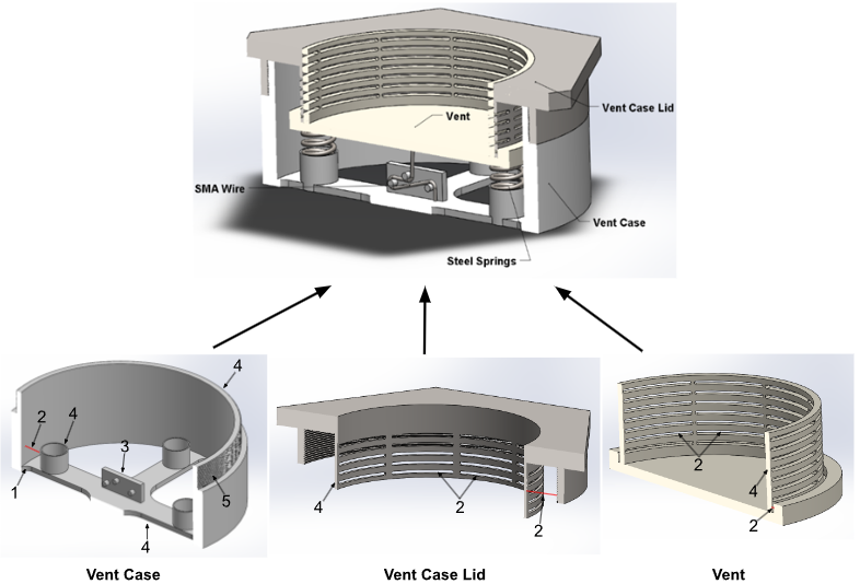
Figure 1: Cross Section of current vent design components labeled with needed changes
Label Descriptions for Figure 1:
Fillets are too small; they need to be at least ⅛ inch in radius.
Spacing (red line) is too small for any tool to fit in the space to machine metal away.
Pulley system is too small to fabricate and cannot be machined due to limited 3-axis machine operation.
The part’s thickness is too thin, which increases the possibility for warping when being machined or heated.
The given space is too small to fabricate proper threads on the part.
The team has come up with a revised design concept that is currently being drafted in CAD. The spring holders are replaced with cylinders that the springs will wrap around. It will provide the same stabilization but be easier to machine. The team is also planning on readjusting the vent mechanism slightly to provide more room to increase the thickness at the bottom of the vent. The holes for venting air will be on the outer cylinder of the vent and the vent lid will be shorter and have larger holes than the previous design. The fillets will be an easy adjustment as it doesn’t impact the functionality of the vent much. The team is still working to address the pulley system for the SMA wire and the threading to put the two vent pieces together. The main idea at the moment is to have pulleys with ceramic liner to reduce contact friction and isolate electrical or thermal charges, but this poses challenges addressed later on the post. As for the threads, if the team can manage to modify the space and wall thickness where the threads will be placed the issue can be fixed.
Lastly, the team met with one of Dr. Song’s students who specializes in controls and electronics to discuss the approach for the design of the control system. The following decisions/design considerations were discussed:
Use either Raspberry Pi or Arduino as the microcontroller
Use ds18b20 temperature sensors to monitor the temperature of the wire as these are highly compatible with microcontrollers and do not require a reference temperature like a thermocouple does. These sensors will be used as feedback for the control system.
Conduct experiments to determine the duty cycle and PWM width needed for heating of the SMA (1.5 V to heat regularly → approximately 10 V is expected to be needed for PWM)
Select a power source. Consider both AC and DC but make sure that it handles at least 10-15 V and can handle surges of very high current and kickback voltage caused by PWM.
Select a solid state relay (SSR) to amplify the current from the microcontroller. Needs to match the power source in terms of AC/DC but needs to have DC on the signal side to connect to the microcontroller. Consider adding a protection circuit to protect the SSR from kickback voltage.
Figure out how to connect everything for the purpose.
Start coding by figuring out how to do PWM for a generic heating element and then modify it to match the SMA once the PWM width and duty cycle have been determined.
For the rest of the semester, the team will work on identifying the correct components, figuring out how to connect everything together, and making a block diagram to represent the function. The code for the control system will be finalized in Capstone II.
Projected Work for Nov 11-25:
Over the next two weeks, the team has several crucial tasks to complete to get the project ready for design review at the end of the semester. The main tasks include conducting SMA wire testing, finalizing the spring stiffness and SMA force analysis, finalizing the FEA model of the SMA wire, conducting a 2D heat transfer analysis in COMSOL, implementing the changes suggested by the machinist, and constructing a final block diagram for the control system that will enable the active venting.
The SMA testing will be done on Monday, November 13th. The team’s goal with this testing is to verify the wire’s recoverable strain, generated actuation force, and force required to reset the wire by straining it after actuation. These measurements will enable the team to finalize the spring selection for the vent mechanism, the selection of pulleys, and the finalization of the FEA. The team also aims to get preliminary values for voltages needed to heat the wire and a starting point for determining the duty cycle and pulse width that will be used for the wire.
The testing shown in Figure 2 will work as follows: The team will cut the SMA wire into 10 [cm] segments. The first 1.5 [cm] will be clamped to a table using a C-clamp. The rest of the 8.5 [cm] will hang freely from the table. At the free end of the SMA wire, the team will attach a fish hook using a ferrule clamp for a secure connection. The team will then use a weight hanger from the experimental methods (EM) lab to be able to hang weights from the wire. First, the team will measure the amount of weight needed to extend the wire by 4% (0.34 [cm]) using a tape measure and small weights from the EM lab. This is the force needed to reset the wire for actuation. Next, the team will use alligator clips and a variac to apply a current to the wire. One alligator clip will be attached at the top and one at bottom of the wire right above the loop to prevent current from flowing to the weights, the current will follow the path of least impedance (effective resistance). According to the resistance of the wire and the current requirements from the specifications, the applied voltage should be around 1.5 [V]. As the resistance of the wire lowers during phase transformation, the team will start with 1.5 [V] and then lower it manually as the wire starts heating up.

Figure 2: Experimental setup for SMA wire analysis
To test the pull force, the team will attach more weights but let them rest on a surface so the wire isn’t strained further. Then the team will apply current to actuate the wire and measure if it can lift the weight while still contracting to its original length. If the wire is longer than its original length plastic deformation has been induced on the wire, meaning the wire was either strained too much or the weight to lift is too heavy.
The spring stiffness calculations and the FEA on the SMA wire will be completed in the days following the testing. The team does not anticipate large challenges with this as the setup for both analyses has been identified and tested in previous milestones. Simultaneously, one member will work on the heat conduction analysis in COMSOL. This method was recommended to the team by Dr. Dong Liu and will be used to determine the area of a battery a single vent can cover. The results will be used to determine the size of the testing case the team will fabricate.
The team will also need to do extensive work on the block diagram for the control system. At this moment, they have illustrated a potential diagram derived from their current ideas. Figure 3 shows the team’s proposed block diagram, which must be reviewed by their project advisor.
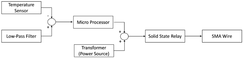
Figure 3: Control system schematic diagram of SMA actuated safety vent
All parts needed for the system have been identified, but the team needs to investigate the required specifications for each part and figure out how they all should be wired together. The goal of the diagram is to provide an overview of how the active venting will work and showcase that the team will be able to heat the SMA wire based on temperature sensors spread out within the battery case. If time allows, the team will also start to model PWM with LED lights and generic heating elements.
Lastly, the team will finalize its selection of vendors for materials. This is a crucial milestone as it will contribute to more precise budget estimations including shipping fees. The team will also identify when components need to be ordered depending on shipping time. By the end of this work period, the team will have completed Milestone 3 (SMA Wire Selected and Tested, Steel Spring Selected, and Conduction Analysis Concluded) and come close to completing Milestone 4 (All technical analyses completed, final vent mechanism with dimensions identified, and bill of materials completed).
The team had a setback as the SMA wire took longer than expected to ship which is why the completion of Milestone 3 has been pushed. However, the team had misunderstood the expectations for the state of the control system for the final design review which buys the team more time. The head capstone instructor, Dr. Christiana Chang, informed the team that a block diagram and details about the control system components and how they go together need to be provided, but the code does not have to be finalized until Capstone II. The team therefore no longer anticipates that time is going to create a large issue. The team anticipates that the biggest challenges are going to be the heat transfer analysis and creating an accurate block diagram because these are the areas where the team has the least expertise. Another small challenge is finding the right fabrication method for the pulley system since it needs to be able to isolate electrical charge and have a radius big enough to prevent stress concentrators on the cable. If the team runs into major issues with the control system, Dr. Song’s student mentioned above has offered to help and also to look over the team’s work at the end to make sure that everything makes sense. The heat conduction analysis in COMSOL has a lot of tutorials online which should be enough to create an accurate 2D model. If a large issue comes up, the team plans on going back to Dr. Liu for advice.


Comments